Bouncing signals off the moon to other folks world-wide is an amazing aspect of our ham radio hobby and being able to put rare grids, States or countries on the air makes it extra fun. As the saying goes, "It's good to be the DX". In the past few years I've used portable, relativity simple stations to put six States (including Alaska and Hawaii) and many rare grids on 6M/2M or 70cm EME helping several hams complete their Worked All States Awards. I thought I'd share some of my experiences and techniques here, including lots of pictures, in an effort to encourage others to give it a try and join the fun. More moonbounce activity is good for everyone.
My philosophy is definitely KISS, that is "keep it simple stupid". I'm just one skinny dude with limited means setting up these portable stations, so rather then add things like cross-polarized Yagis with elaborate switching regimes or SDR receivers using MAP65 (which are fantastic tools) I opt for simple, light weight, easy assembled Yagis and take advantage of that fact that by my choice of operating location I'm a fairly rare station attracting lots of callers and that eventually Faraday rotation is going to give folks a chance to work me. This is especially true if I can plan to be on for several moon passes.
A few concrete examples of what can be achieved: On a two recent trips to Yellowstone Park (DN44lw) I set stations up at a trail head and operating for about six hours each time. I worked 57 folks on 2 meter EME and 17 folks on 70cm EME. Now that is a lot of bang for the buck!
 |
| Fortunately a portable EME station doesn't have to be neat. A look at my KH6/KB7Q 70cm lash-up using a borrowed FT-897D. |
 |
| 6M EME from Alaska 2010, that salt water moonset horizon produced 33 contacts and quite the view.. |
 |
| 13wl 70cm Yagi on the Beartooth Plateau, Wyoming. I worked 18 stations. |
 |
| Yellowstone Park (DN44lw) - Two 9 element 2M Yagis with manual elevation/azimuth. It takes about 45 minutes to assemble. |
 |
| This quick and simple single 9wl Yagi set up netted 19 70cm EME QSOs from DN85gu, South Dakota. |
The most defining design goal of my portable stations was to decide just how much transmit power I can run in the wilds away from the utility mains. I already owned a Honda EU2000i generator that I know from experience will start to struggle running more then a 800 watt station, especially when you account for the altitude here in the western USA that de-rates the horsepower of the unit and its ability to make watts. It also turns out the excellent LDMOS SSPA amplifier modules offered by W6PQL pretty much match that output with their superb efficiency. Another consideration is weight, these generators are about 50 pounds which is what I can comfortably lift in and out of my truck. Yamaha also makes some excellent generators. I'd estimate that my total power demand is around 1,300 watts for the amp, radio, computer, and perhaps a lamp.
As a bonus limiting the power output to around 800 watts means that I can run the station off a single 120 vac connection if I find a campground with a mains power pedestal.
You would think having to run off a generator is a real limitation. Not so. The Honda EU2000i is an excellent inverter style unit that doesn't make RFI. Most of the operating locations I select to are incredibility quiet compared to our home neighborhoods given all the RFI "smog" these days. I've worked several single Yagi stations on 2M with -26 to -28 decodes. It's not unusual for me to "see" 15 stations at a time in the WSJT waterfall display.
I run synthetic oil in my generator and feed it high test gasoline that does NOT contain ethanol when I can find it. I can run a solid five hours on each tank of fuel, that's about a gallon of gasoline, and I do not use the "economy throttle setting" as the generator can't pick up speed fast enough on transmit to keep from kicking off line and shutting the whole station down. At altitude I can borrow a second Honda generator and run the two unit in parallel using a simple cable I found on the Internet and bump my power out to 850 watts. I found that re-jetting the generator's carburetor helps immensely at high altitude out here in the western States.
 |
| This picture pretty well illustrates my power plant options. 120 vac only. |
Between the local hardware store, eBay and the Internet I worked out a solution that is quick to assemble, and rugged enough to keep the antenna up in most any wind. I designed the tripod around this piece that forms the tripod's apex I found on eBay. This was a terrific discovery. Sorry for the non-metric units of measure.
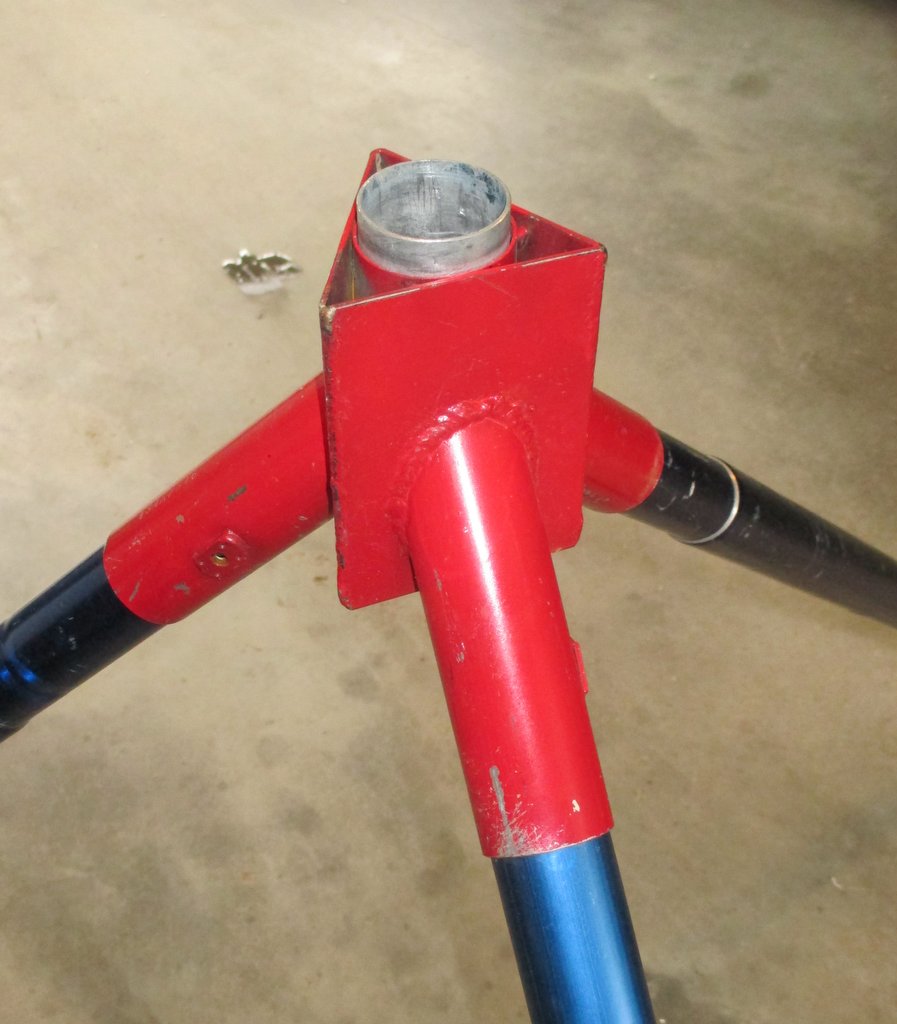 |
| This tripod apex is made of steel. It is plenty stout. |
For azimuth read out I hose clamp a wire pointer to the vertical mast and slipped a laminated compass rose onto the aluminum bearing.
 | |
| KISS philosophy in action. The beamwidth of the array means only re-aiming every 20 minutes. |
 |
| Tripod held in tension against mother earth. |
 |
| Don't forget the maul to drive these monsters. |
 |
| For the elevation angle I just sight along a cheap carpenters inclinometer from Amazon. |
EME signals are shockingly weak, even using JT65 mode, so a lot of careful effort goes into the receive side of things. If you're going to put out the energy and cost to assemble a portable station you might as well design it from the start having a quality pre-amp out at the feed point of your antenna system for the very best noise figure. Of course that entails a relay switching system to keep it from being damaged when transmitting. This means building a relay/pre-amp box. I followed the tried and true EME method of using two relays and running the transmit line and the receive line as separate runs of coax. I built my unit in a BUD AC424 (12x8x3 inch) chassis with a BPA-1519 cover plate.
I use a Tohsu CX600N-12 relay to handle the transmit side of things, and a CX-230-12 in front of the pre-amp to switch it into a 50 ohm termination during transmit cycles. There are better relays for isolation and power handling on eBay, but as my transceiver runs off a 13.8 vdc power supply I wanted to avoid having to provide a separate 24 or 28 vdc line out to the relay box for these surplus units. KISS remember. At 800 watts on 2 meters or 500 watts at 70cm the CX-600N relay works fine as long at the SWR is low, and they are readily available. In the field I carry a spare CX600N and a pre-amp.
One thing I do that seems odd is that I energize the relays to transmit. This means the front end of the pre-amp is normally connected to the array most of the time. Being a portable setup the pre-amp is not exposed to static charge for long periods of time, and I like the extra tension on the wiper of the relay that being energized on the transmit side provides for that 800 watts. When stored I screw a 50 ohm termination onto the feed point side of the relay/pre-amp box to protect the pre-amp. I'd announce here that I've never lost a pre-amp, but Mr. Murphy would hear me.
ARR pre-amps are a good initial choice at about a .55 db noise figure, but WA2ODO, K4EME, and WD5AGO make superior state-of-the-art units for about double in price and half the noise figure. Looking at my pre-amp box you can see I have a couple of N/BNC adapters to eliminate to improve my noise figure a bit. This article from KL6M is a bit dated, but is an excellent EME relay configuration tutorial.
 |
| I have the CX600N relay and the pre-amp's power leads on connectors for easy field replacement. |
 | |
On 70cm I now use an Icon IC-9700, and as I haven't discovered how to separate the TX/RX leads yet I use a third relay (CX-230-12) at the transceiver's coax socket to do the switching. I use the rig's USB port directly for rig control and audio eliminating the need for the microHam interface described above. KISS remember!
 |
| Now that's worth the careful effort on the receive side - I count about 15 signals off the moon with 2x Yagis on 2M. |
At this power level recent designs from W6PQL and F1JRD have made power vacuum tubes like the 3CX800AJ obsolete. Tubes are out, and LDMOS solid state devices no bigger then your little finger are in. Units like the BLF188XR can stand high SWR while generating a kilowatt with 70% efficiency from a single 48 VDC switching power supply. Amazing. This makes generating power in the field a snap compared to lugging around a heavy high voltage/filament power supply and power tube amp deck.
Amps designed around these LDMOS devices have proven to be quite reliable IF you pay attention to cooling and never, ever over-drive them. The previous sentence is worth reading again.
Here in the States Jim, W6PQL offers everything from parts, to kits, to assembled amps. For me what worked best was buying an assembled and tested RF module with an attached heatsink and mounting it on a 12"x8"x3" chassis and wiring in the support circuits myself. I ended up with small, relatively light weight units that produce 800 watts on 2M, and 500 watts on 70cm. So for about half the cost of a commercial unit I have some rugged amps. Certainly not elegant, but they works great - just pay attention to cooling, and drive levels.
 |
| 2M 800 watt SSPA. Note the massive heatsink and the 4 inch 85 cfm fan, and vent holes for second, smaller fan inside. |
 |
| It was tight, but it all fits. I decided to use an old time SPST power relay to turn the 48 vdc on/off after a few power FET failures. |
Here's a look inside the 500 watt 70cm amp that uses a BLF184xr LDMOS device. No input attenuation pad on this one - seven watts of drive from the IC-9700 transceiver makes 525 watts output. This was the second unit built, so it took under half the time because I already had a good idea about part locations.
 |
| 70cm 500 watts LDMOS amp. I must have gotten a great price on yet another 12"X8"X3" chassis. |
 |
| Meanwell RSP1500-48 power supply, typical of what you can find on eBay. |
Using digital mode JT65 on EME means the computer has to have time accurate to within a second to work well on moonbounce. Many times while operating portable out here in the western USA I don't have Internet access to sync the time. Rather I use my trusty Garmin GPS and some excellent software to get the time sync done.
BktTimeSync by IZ2BKT is hard to beat for time syncing. My laptop holds time well enough that I only need to sync once at the start of my operating.
 | |
| If you use IZ2BKT's fine shareware software make a donation please. |
 |
| My GPS will even tell me what grid I'm in! |
There are lots of bits and pieces to bring along on a portable EME outing. To stay organized and to avoid leaving a critical cable back home I use Rubbermaid tubs to sort and organized my gear. I note the contents of each tub on the lid. It works well for me as I'm often doing two bands on moonbounce with the added complexity of parts specific to each band. Of course when I fly off to a location rather then driving the tub technique gets reduced to a piece of checked luggage.
 |
| Probably not worth much at a Pawn Shop, but priceless in the field. My organizational scheme. |
 |
| Wing nuts work well. Just one of several boxes of organized spare parts for when I fumble-finger something into the dirt. |
My assumption for portable EME on 6 meters thru 70cm is that we'll be using digital mode JT65a on 6M and JT65b on 2M and 70cm. This means you need to master the WSJT software by Joe Taylor, K1JT. This single piece of software has revolutionized EME for small stations with its ability to extra signals from below the noise level.
Here are a few tips that make all the difference in successful decoding:
Set the Sync field to a negative number, otherwise you're invoking a squelch effect.
If you see signals drifting on the waterfall display (especially on 70cm) check the AFC box
Use an up-to-date call3.txt file, a good one is found here
Set the decode menu to "include average in aggressive deep search"
On 70cm account for the up to 1 KHz Doppler shift, look far and wide on the waterfall display
 |
| Typical WSJT settings. When locked on a station in a pile-up I often reduce "Tol" to 25 or even 10 Hz. Note sync setting. |
Some folks like to work CW on 70cm, but other then DL9KR who has a stunning CW signal, you'll waste precious time trying to use a mode that is at least 10 db down compared to JT65.
Most folks are running WSJT 10 r6088 right now, but development on WSJT - X 1.7 is finishing up, and will be a major program make-over, it is rumored to have an improved JT65 decoding scheme. We're getting a new mode too, QRA64, that promises a few db better decoding performance. Stay tuned for news this fall. We're so lucky to have such a dedicated programing team lead by Joe Taylor, K1JT developing these tools for our enjoyment.